Counter Relay Circuit Diagram . Relays are magnetic electromechanical devices with two primary purposes: To isolate different circuit voltages, and to form larger complex. So, we have decided that in this tutorial, we are going to “binary counter circuit diagram”. In this circuit a timer with cyclic on off operations is designed. This circuit uses very basic components like 555 timer and 4017. There are a variety of electrical and electronic. In this post i have explained the making of simple delay timers using very ordinary components like transistors, capacitors and. Electronic relay switch circuit diagram and its working. The circuit needs two major elements as its key components, first the 555 timer.
from www.circuitsgallery.com
Relays are magnetic electromechanical devices with two primary purposes: So, we have decided that in this tutorial, we are going to “binary counter circuit diagram”. There are a variety of electrical and electronic. To isolate different circuit voltages, and to form larger complex. In this post i have explained the making of simple delay timers using very ordinary components like transistors, capacitors and. The circuit needs two major elements as its key components, first the 555 timer. Electronic relay switch circuit diagram and its working. This circuit uses very basic components like 555 timer and 4017. In this circuit a timer with cyclic on off operations is designed.
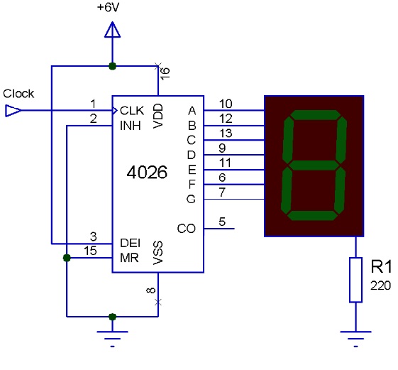
Simple 4026 Manual Digital Counter Circuit With Reset and Pause
Counter Relay Circuit Diagram So, we have decided that in this tutorial, we are going to “binary counter circuit diagram”. The circuit needs two major elements as its key components, first the 555 timer. This circuit uses very basic components like 555 timer and 4017. Relays are magnetic electromechanical devices with two primary purposes: There are a variety of electrical and electronic. Electronic relay switch circuit diagram and its working. In this circuit a timer with cyclic on off operations is designed. In this post i have explained the making of simple delay timers using very ordinary components like transistors, capacitors and. To isolate different circuit voltages, and to form larger complex. So, we have decided that in this tutorial, we are going to “binary counter circuit diagram”.
From control.com
Relay Circuits and Ladder Diagrams Relay Control Systems Textbook Counter Relay Circuit Diagram In this circuit a timer with cyclic on off operations is designed. So, we have decided that in this tutorial, we are going to “binary counter circuit diagram”. Relays are magnetic electromechanical devices with two primary purposes: Electronic relay switch circuit diagram and its working. This circuit uses very basic components like 555 timer and 4017. In this post i. Counter Relay Circuit Diagram.
From manualfixklein.z19.web.core.windows.net
Circuit Block Diagram Of Counters Counter Relay Circuit Diagram This circuit uses very basic components like 555 timer and 4017. In this post i have explained the making of simple delay timers using very ordinary components like transistors, capacitors and. In this circuit a timer with cyclic on off operations is designed. The circuit needs two major elements as its key components, first the 555 timer. To isolate different. Counter Relay Circuit Diagram.
From circuitdigest.com
How a Relay Module Works and Interfacing a Single Channel Relay Module Counter Relay Circuit Diagram Electronic relay switch circuit diagram and its working. Relays are magnetic electromechanical devices with two primary purposes: To isolate different circuit voltages, and to form larger complex. In this circuit a timer with cyclic on off operations is designed. In this post i have explained the making of simple delay timers using very ordinary components like transistors, capacitors and. There. Counter Relay Circuit Diagram.
From instrumentationtools.com
Relay Latching Circuit using Push Button Instrumentation Tools Counter Relay Circuit Diagram In this post i have explained the making of simple delay timers using very ordinary components like transistors, capacitors and. This circuit uses very basic components like 555 timer and 4017. To isolate different circuit voltages, and to form larger complex. In this circuit a timer with cyclic on off operations is designed. Relays are magnetic electromechanical devices with two. Counter Relay Circuit Diagram.
From manualdbkathrin.z19.web.core.windows.net
Master Trip Relay Circuit Diagram Counter Relay Circuit Diagram Electronic relay switch circuit diagram and its working. The circuit needs two major elements as its key components, first the 555 timer. There are a variety of electrical and electronic. This circuit uses very basic components like 555 timer and 4017. In this post i have explained the making of simple delay timers using very ordinary components like transistors, capacitors. Counter Relay Circuit Diagram.
From schematicpartclaudia.z19.web.core.windows.net
Counter Relay Circuit Diagram Counter Relay Circuit Diagram The circuit needs two major elements as its key components, first the 555 timer. To isolate different circuit voltages, and to form larger complex. In this post i have explained the making of simple delay timers using very ordinary components like transistors, capacitors and. Relays are magnetic electromechanical devices with two primary purposes: Electronic relay switch circuit diagram and its. Counter Relay Circuit Diagram.
From circuitpartehrlichmann.z19.web.core.windows.net
Electronic Relay Circuit Diagram Counter Relay Circuit Diagram This circuit uses very basic components like 555 timer and 4017. The circuit needs two major elements as its key components, first the 555 timer. Electronic relay switch circuit diagram and its working. Relays are magnetic electromechanical devices with two primary purposes: In this post i have explained the making of simple delay timers using very ordinary components like transistors,. Counter Relay Circuit Diagram.
From manualdiagramcecil.z1.web.core.windows.net
4 Bit Counter Circuit Diagram Counter Relay Circuit Diagram To isolate different circuit voltages, and to form larger complex. Relays are magnetic electromechanical devices with two primary purposes: In this post i have explained the making of simple delay timers using very ordinary components like transistors, capacitors and. The circuit needs two major elements as its key components, first the 555 timer. Electronic relay switch circuit diagram and its. Counter Relay Circuit Diagram.
From www.circuitdiagram.co
simple relay circuit diagram Circuit Diagram Counter Relay Circuit Diagram Electronic relay switch circuit diagram and its working. So, we have decided that in this tutorial, we are going to “binary counter circuit diagram”. To isolate different circuit voltages, and to form larger complex. In this post i have explained the making of simple delay timers using very ordinary components like transistors, capacitors and. There are a variety of electrical. Counter Relay Circuit Diagram.
From www.vrogue.co
Wiring Diagram 4 Pin Relay Classic Inlines 12v Timer vrogue.co Counter Relay Circuit Diagram To isolate different circuit voltages, and to form larger complex. In this post i have explained the making of simple delay timers using very ordinary components like transistors, capacitors and. Electronic relay switch circuit diagram and its working. Relays are magnetic electromechanical devices with two primary purposes: In this circuit a timer with cyclic on off operations is designed. This. Counter Relay Circuit Diagram.
From wiringdiagramall.blogspot.com
Contactor Wiring Diagram With Float Switch Counter Relay Circuit Diagram The circuit needs two major elements as its key components, first the 555 timer. In this post i have explained the making of simple delay timers using very ordinary components like transistors, capacitors and. This circuit uses very basic components like 555 timer and 4017. To isolate different circuit voltages, and to form larger complex. So, we have decided that. Counter Relay Circuit Diagram.
From resolutionsforyou.com
How to Wire an Omron MY2NJ Relay A Comprehensive Diagram Guide Counter Relay Circuit Diagram This circuit uses very basic components like 555 timer and 4017. In this circuit a timer with cyclic on off operations is designed. In this post i have explained the making of simple delay timers using very ordinary components like transistors, capacitors and. To isolate different circuit voltages, and to form larger complex. Electronic relay switch circuit diagram and its. Counter Relay Circuit Diagram.
From circuitpartehrlichmann.z19.web.core.windows.net
Relay Circuit Diagram 24vdc Counter Relay Circuit Diagram Relays are magnetic electromechanical devices with two primary purposes: In this circuit a timer with cyclic on off operations is designed. This circuit uses very basic components like 555 timer and 4017. So, we have decided that in this tutorial, we are going to “binary counter circuit diagram”. The circuit needs two major elements as its key components, first the. Counter Relay Circuit Diagram.
From circuitmanualkohler.z19.web.core.windows.net
5 Pin Relay Circuit Diagram Counter Relay Circuit Diagram In this post i have explained the making of simple delay timers using very ordinary components like transistors, capacitors and. There are a variety of electrical and electronic. This circuit uses very basic components like 555 timer and 4017. The circuit needs two major elements as its key components, first the 555 timer. In this circuit a timer with cyclic. Counter Relay Circuit Diagram.
From theinstrumentguru.com
Relay wiring diagram What is Relay? THE INSTRUMENT GURU Counter Relay Circuit Diagram In this circuit a timer with cyclic on off operations is designed. So, we have decided that in this tutorial, we are going to “binary counter circuit diagram”. There are a variety of electrical and electronic. The circuit needs two major elements as its key components, first the 555 timer. In this post i have explained the making of simple. Counter Relay Circuit Diagram.
From wiringengineabt.z19.web.core.windows.net
Digital Circuits Diagram Counter Relay Circuit Diagram Electronic relay switch circuit diagram and its working. To isolate different circuit voltages, and to form larger complex. This circuit uses very basic components like 555 timer and 4017. There are a variety of electrical and electronic. In this circuit a timer with cyclic on off operations is designed. So, we have decided that in this tutorial, we are going. Counter Relay Circuit Diagram.
From fixliberic.z19.web.core.windows.net
4 Hour Timer Circuit Diagram Counter Relay Circuit Diagram The circuit needs two major elements as its key components, first the 555 timer. Relays are magnetic electromechanical devices with two primary purposes: So, we have decided that in this tutorial, we are going to “binary counter circuit diagram”. To isolate different circuit voltages, and to form larger complex. Electronic relay switch circuit diagram and its working. There are a. Counter Relay Circuit Diagram.
From manualwiringschaefer.z19.web.core.windows.net
Solid State Relay Schematic Circuit Counter Relay Circuit Diagram Electronic relay switch circuit diagram and its working. In this circuit a timer with cyclic on off operations is designed. So, we have decided that in this tutorial, we are going to “binary counter circuit diagram”. In this post i have explained the making of simple delay timers using very ordinary components like transistors, capacitors and. The circuit needs two. Counter Relay Circuit Diagram.